Joists
As the process of constructing a traditional brick and mortar house is undertaken, the first carpentry specific task that is carried out is the installation of timber joists. This task may be carried out to form the floor joists of the ground or first floor in a 2-storey house, or to form the ceiling joists of the ground floor in a bungalow - depending on the exact construction criteria.
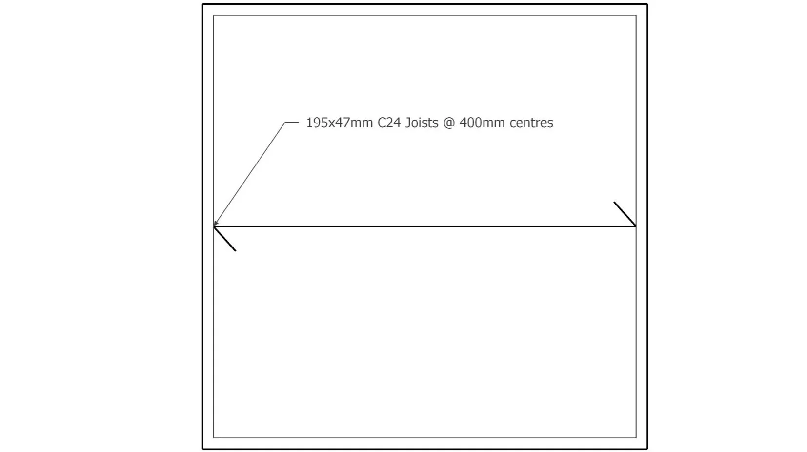
Unless working to a specific joist plan that outlines the exact layout of the joists, a suitable layout is discerned from the standard plans. For floor systems formed from engineered joists, it’s common for a plan to be provided by the manufacturer to aid in the assembly process. The engineers’ drawing will display the information relating to joists in a simple and clear format, as shown in the illustration. This notation displays the direction of the span of the joists, as well as the exact timber dimensions, type, and spacings. Each separate span of joists will be displayed on the drawing. More detailed information will be found in the specification.
What is a joist?
A joist is a perfectly horizontal structural member that spans between two load bearing components. Joists come in many different specifications, sizes, shapes, and materials. Solid timber is the most common and traditional of the selection; the size to be used being specified by a structural engineer in accordance with the structural calculations. Other systems such as made-to-order TJI joists, metal webbed joists, and aluminium joists can be called for in the specification depending on the criteria of the build. Joists are installed at regular intervals within a room (typically 400mm/16” centres) in order to support the installation of subfloor sheathing. Before the introduction of modern insulation and damp protection, the ground floor of residential properties were often formed through the use of timber joists. This is less common in modern construction, with insulated concrete slabs being a more suitable selection in terms of heat retention and rot protection. In standard residential construction, timber joist systems are installed to form the upper floors of the building, as they are lightweight and cost effective in comparison to alternative concrete systems. In these instances, the underside of the joists support the installation of plasterboard/drywall that forms the ceiling in the rooms below. In most roof assemblies, the ceiling joists of the top floor of the building serve also to prevent the wall plates from being pushed outwards.
What are the criteria for the installation of joists?
When joists are installed to create a floor system, they distribute the weight of the subfloor and any load applied across it towards the load bearing supports, typically a vertical internal wall below. Joists that are installed to form a floor system will often be referred to as floor joists. These floor joists are sheathed with a subfloor material, typically 600mm x 1200mm sheets of chipboard flooring in modern UK construction. 100mm of fibreglass quilt insulation is installed between the joists as standard requirement for heat retention and soundproofing. First floor joist sizes are calculated according to the weight of the subfloor to be supported, the estimated load of furniture and people that will be walking upon them, and the weight of the plasterboard that forms the ceiling of the floor below.
Ceiling joists describe joists that primarily form a surface from which to hang a ceiling finish like plasterboard. When standing in any room that has joists above it, the argument could be made that they are ceiling joists, though more often than not the term ceiling joist refers to the top layer of joists within a building, for no other reason than to distinguish between the two. Ceiling joists that form part of the assembly of a pitched roof are not necessarily load bearing, though if a loft or attic space is designated within the roof then the calculations for the depth of the joists will allow for this. The most important function of ceiling joists within a pitched roof is to prevent the spread of the roof, by resisting the load that is directed downwards through the rafters towards the plate. By installing ceiling joists that span from plate to plate, they become tied together, preventing the walls from spreading.
All joists should be installed at specified centres (typically 400mm) in accordance with the structural regulations unless stated otherwise. Double skewed fixings should hold the ends of the joists to a plate if applicable, and some form of blocking should be installed at the centre point/third points of the joists. The joists should be installed crown up, with a maximum crown above the plane of the floor of about 3mm. This will ensure that the finished floor surface remains flat to a suitable tolerance. Excessively crowned joists should be cast aside, though those that are only slightly over this guideline can have their high spot planed off. In contrast, the allowable deflection of floor joists in accordance with the NHBC guidelines states a maximum deflection of 0.003 x the span of the joists.
● “no more than 0.003 x the span for the combined bending and shear based on the total dead and imposed loads, with a maximum deflection of 14mm where strutting is provided, or 12mm where strutting is not provided.”
Though these guidelines exist as hard and fast rules, care should be taken to install the joists perfectly level with minimum deflection.
Where joists bear onto the internal skin of cavity masonry, it's important for the length to not project into the cavity space of the masonry. Excess length within the cavity can create a snag for dropped mortar, which in turn can lead to cavity bridging and internal damp/mould/rot issues.
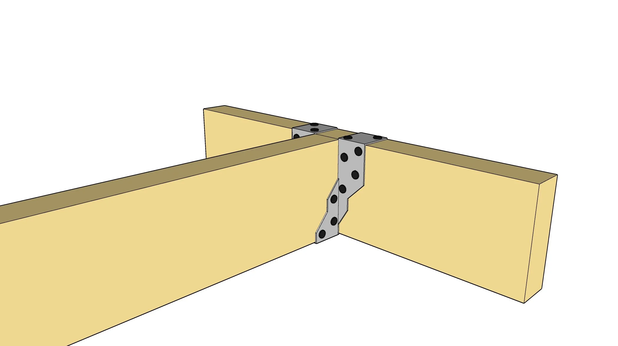
Where joists are placed into metal joist hangers, the joist must be fully seated within the hanger, taking advantage of the full bearing.
How are joists installed?
When installing joists, the first step is to identify and procure the correct size of timber or product in accordance with the specification. The engineer will specify the direction of the span, the dimensions of the timber, and the spacings for the joists on the floor plan. A common spacing for most timber components is 400mm(16”) centres , though 600mm(2‘) centres can sometimes be called on depending on the dimensions of the timber and thickness of the subfloor. The span of the joists is indicated on the plan via the directional arrows. Ascertaining the relevant information from the drawings and specification is crucial to carry out the successful installation of joists in compliance with the desired outcome and criteria of the project.
In this example, the joists, which will form the first floor of a standard cavity masonry structure, are bearing directly on the inside skin of the masonry, as opposed to on a wall plate or through being supported via hangers. This is a common setup, with the ends of the joists being blocked in after installation, and the cavity masonry continuing upwards around the joists. There is no requirement here for a timber plate under the ends of the joists, due to the fact that the ends of the joists will be held captive by the masonry, as well as the fact that it is not structurally suitable to continue masonry upwards on top of timber (generally speaking).
With the correct materials identified, the layout of the joists can be undertaken. When bearing on masonry, the ends of the joists are held captive by the masonry after installation. When installing joists in this fashion, layout rods are used to temporarily hold them in the correct place until the bricklayers have built up around them. The layout of the joists can be marked out on these rods, which can in turn be used to space the joists, as opposed to performing the layout on the masonry itself. Copies of the first rod can be made to maintain the correct layout at both ends of the span of joists, as well as through the centre of the span.
As is typical, the layout will begin from one appropriate wall within the room. The exact wall doesn’t matter specifically, and can be chosen depending on an appropriate criterion, though it’s important that all of the following layout within the room starts from the same registration point. The rod is laid on the inside skin of the masonry, perpendicular to the span of the joists, and butted up to the inside of the internal skin as it returns around the corner. This point will be used as the reference point for the other layout rods.
In order to promote suitable ventilation and prevent mould growth on the timber or the wall, an air gap of 50mm (2”) is required between any joist that sits directly next to a wall. As is going to be the case about 95% of the time, there are two full length joists that are going to sit next to a wall.
Measuring in from the internal skin, strike a mark 50mm from the wall. Marking a cross or some form of personalised layout marking denotes the position of the joist in relation to the line. In this scenario, the engineer has specified for the joists to be laid out at 400mm centres, which means the distance from the centre of the thickness of each joist to the next should be 400mm and should not exceed this distance. At any recurring set distance, the measurement taken from the edge of a joist to the same edge of the next joist is also the same distance as the centre to the next centre. This is an important factor to note, as physically hooking a tape over one edge of a joist and measuring to the next is far easier than literally measuring 400mm centre to centre.
As with any component or system that is to receive a sheathing material, we must ensure the layout of the remaining joists accommodates the subfloor material that will be laid upon it. In the mindset of renovations and refurbs, it isn't the end of the world if the end of a full 2.4m floorboard doesn’t land directly upon a joist, as we can always cut the board down to start a row or add solid blocking to support the end of a board in the middle of a run. This is a common situation with renovations as existing joists are not always going to be set out for our floorboards in their new configuration. That being said, when constructing extensions or new builds, as is the case in our example, we have the opportunity to set the joists out specifically for our flooring system.
When floorboards are laid, a 10mm expansion gap must be allowed for around the edge of the system to prevent buckling in the floor due to expansion, and so we must allow for this gap in the layout of our joists. The diagram shows a close-up detail of how the beginning of our flooring system will look. Using this information, we know that the floorboard will start 10mm away from the wall, and sail 40mm over the end of the joist. By the time the finished masonry is dry lined, and the skirting is installed, this unsupported outside edge of flooring is not accessible to stand on, with the very outside of the accessible subfloor floor supported directly by the outside joist. Due to the overhang of the board, and the required 50mm air gap, the first and often last joist within a masonry joist system are not perfectly “on centre”. Therefore, we must mark the location of the second joist in relation to the start of the floorboards in order to define a good point to pull repeated 400mm increments off of. This simply involves measuring 400mm in from the point at which the flooring system starts. This mark denotes the very centre of the joist. By measuring backwards half the thickness of the joist, we can see the outside edge of where the joist will sit. Running a saw on this line to create a shallow groove creates a notch for the hook of the tape measure to sit in. From this fixed point, increments of 400mm can be marked, with an appropriate mark denoting the side of the line that the joists will sit. If accuracy is maintained during the layout and installation, a floorboard placed on top of the joists will land 10mm away from the wall, with the other end landing half on one of the joists.
As we approach the far end of the room, bear in mind that the last joist will also sit 50mm away from the wall. As we approach this point, any distance under 400mm is acceptable, but anything over span must be addressed by continuing the 400 centres as far as possible before reaching the end joist. If the distance between the last 2 joists is slightly over span don’t try to split the difference between the two with a joist, just continue the incremental layout from one end, it looks more professional. If the layout rod is not long enough, we can overlap an additional rod to extend the length.
With the layout rod complete, additional copies can be made, typically one for the far side of the room, and one for the middle of the span of the joists. The joists can be cut to length at a bench or cutting station or trimmed to length once they are laid on the masonry, depending on the amount of area we have to work with. The exact length of the joists should be the distance between the two outside edges of the internal masonry. This measurement is known as the “span”, as is any measurement that is taken from back of plate to back of plate. It is important the joists do not project beyond the back of the internal skin and into the cavity, as this can lead to cavity bridging and potential damp issues. A tape measure can be used to check that the span of the room is consistent along the length of the room. Ideally the span will be consistent, and all of the joists can be cut to the same length. If not, each joist must be cut to the appropriate length. Each joist can be laid flat roughly in the correct position, with the crown of each timber all facing the same direction. With all of the timbers laid in place, the installation can begin.
Each joist is flipped upwards in the correct orientation with the crown facing upwards. The layout rods can then be laid on top of the joists towards the outer edges of the masonry. The rods will be temporarily fixed to the tops of the joists using half set nails or screws in order to hold the joists in the correct alignment. It is important to position the rods away from the internal skin to provide suitable clearance for the bricklayers as they block up around the end of the joists. A comfortable distance of around 50mm from the inside skin of masonry is suitable. As long as the first joist maintains an eve 50mm gap between the internal skin, the layout rods at each end of the joists will maintain the correct O/C layout throughout the room.
If the room is not square, we may find that by the time we reach the far end of the run, a small deviation may have occurred, possibly as much as a few inches in an extreme scenario. In this instance, we must follow our layout right to the very last joist, at which point we will swing this joist round to maintain a 50mm gap away from the wall. This will ensure that an even overhang of the floorboard will occur over the edge of the last joist, preventing accidental splitting or breaking of the floorboard.
If the joists are being installed as a part of a roof system and are bearing on a timber wall plate, then the layout rods are not strictly necessary, as the layout can take place on the plate, with the joists being fixed directly to it. Layout rods can still be useful here though, to transfer the layout from one plate to the other, as well as keeping the joists upright before the installation of the solid blocking and the rafters.
When carrying out the installation of joists, the load bearing requirements are calculated by the engineer, with sizes being specified on the drawings. Generally speaking, the greater the load that is bearing on the joists, the deeper or thicker the joists must be. Here is an example of a general purpose span table, displaying the approximate size joists for certain load capacities. Alongside these important calculations that meet the requirements of the build, there are some quick methods of estimating joist depth for preliminary cost and material purposes. Roughly, the thickness in millimetres for a joist, is the span of the room in millimetres, divided by 20, plus 20mm. This value should be rounded up to the nearest dimensional size to determine approximately the correct depth of timber. The same outcome can be achieved using the imperial formula - span in feet, divided by 2, plus 2, to return the depth in inches. As a brief note, the ceiling joists of a building that form part of the roof structure are typically less deep than the floor joists, as the loft space is intended to receive less load in contrast to the rooms below bearing the weight of furniture and people.
When installing joists as a part of a ground floor system, the approach differs slightly, in order to combat the risk of rising damp and rot. Before the implementation of modern damp proofing solutions and concrete/masonry-based floor systems, suspended timber ground floors were very common in traditional British residential properties built within the last few hundred years. This type of floor system can still be called for in modern construction as a less expensive option in contrast to the other types of ground floor systems, and it benefits in the modern age from the implementation of current damp proofing and insulative technologies within its design.
The premise of a suspended ground floor sees the joists supported via multiple honeycomb sleeper walls that sit within the footprint of the cavity masonry. The joists do not come into contact with the cavity masonry, reducing the risk of rot caused by rising damp that might affect the cavity. The sleeper walls are spaced evenly throughout each room to adequately support the joists. In older properties, these joists are typically 4” timbers, which are quite small compared to todays standards, and so multiple sleeper walls were spaced out to take the whip out of the span. Typically, the timbers do not span more than 1200mm between the sleeper walls.
The sleeper walls are built in a honeycomb fashion, with the holes in the masonry providing ventilation below the suspended floor. Air bricks installed in the cavity masonry allow air to flow freely below the floor, providing suitable ventilation and preventing rot from occurring. There is a critical ventilation issue that occurs in a very specific scenario pertaining to old suspended floors that we shall look at shortly. In traditional buildings, it was very common for the oversight to be left exposed, with the sleeper walls being built on top of corbel brickwork footings that sat directly on the soil. As time moved forwards it was more common for a thin layer of concrete blinding to be added on top of the soil, with the sleeper walls being erected on top of this. That being said, both of these scenarios lacked any substantial damp proofing, relying predominantly on slate or old-school damp proof course. In areas with a high water table or in buildings that suffer from inadequate drainage solutions, this lack of suitable damp proofing can lead to rising damp issues within the sleeper walls themselves. These traditional suspended floors did not include insulation, leading to a loss of heat within the home through the ground floor.
In modern times, the same construction methods apply, though the execution involves the use of contemporary damp proofing products and techniques. When the cavity wall begins to emerge from the ground at the start of the build, a typical concrete slab is prepared to form the foundation of the sleeper walls. A hardcore base is whacked on top of the reduced oversight, with blinding sand, DPM, and concrete to follow. The top of the concrete can be calculated by stepping down from the desired floor height, with the total height consisting of the thickness of the flooring, the depth of the joists, about 3 courses of brick for the sleeper wall, and possibly the thickness of a timber plate bedded on the sleeper wall. The exact setup is dependant on the specific scenario. If a timber plate is bedded on top of the sleeper wall to provide a fixing point for the joists, then DPC is installed under the bed of mortar directly on top of the sleeper. If no plate is present, then the joists sit on top of a layer of DPC directly on top of the sleeper wall. This DPC in combination with the prepared slab and DPM underneath provides suitable damp proofing to combat the potential for rot. Insulation can then be installed between the joists, with a layer of vapour barrier possibly being placed on top of the joists before the floorboards are installed, though this is dependant on the criteria of the project. Air bricks and telescopic air vents are installed within the new cavity masonry to allow for the air to flow freely under the floor and prevent rot/mould growth.
The critical issue with old suspended floors stem from a lack of ventilation below the floor. Traditional properties were not built with cavity insulation. The primary purpose of the cavity within the masonry is to prevent moisture from penetrating inside the building, though the lack of insulation did not promote heat retention. The air bricks installed at the low section of the building allowed air to circulate through the cavity as well as below the suspended floor. Though drafty and often cold, this ventilation eliminated the conditions for rot and mould to thrive in. Fungi, specifically dry rot in this case thrive in damp, poorly ventilated areas. Though potentially damp below the floor, the suitable air flow helped to evaporate the excess moisture and prevent the growth of dry rot fungi. When remedial cavity insulation was introduced, namely blown mineral wool, the option for many older homes without cavity insulation to become insulated lead to a boom in such a practice. In my experience, generally due to a lack of proper preparation, this has spelled disaster for more properties than it has done good.
Firstly, the point of the cavity is to prevent external moisture from penetrating to the inside of the building. The physical gap of the cavity prevents water from making its way to the inside skin, and the design of wall ties and the implementation of modern cavity insulations work towards this goal similarly. By blowing full fill cavity insulation into the cavity, water is able to track through the cavity and through the internal skin. On numerous occasions during demolition work, I have demolished existing external cavity masonry to find that the blown mineral wool is saturated with moisture. Unsurprisingly, there are typically mould/damp issues on the inside of the properties corresponding to the areas of wet cavity insulation.
Secondly, if the cavity is not sealed off in the roof space before the insulation is blown in, it can spill out into the loft space, making a mess, and possibly blocking the existing roof ventilation. It can also touch the felt, leading to condensation issues and general poor ventilation in the loft space. Finally, and most relevantly to this topic, the blown insulation will fall down the cavity and block the air vents that are installed towards the bottom of the building. In the past, the internal and external air bricks were not necessarily connected together like they sometimes are in modern construction, allowing the blown insulation to fall down and fully block the air vents. As this happened around the perimeter of the building, the amount of ventilation within the cavity and below the suspended floor reduced dramatically, creating a damp, low-ventilation environment. This environment is the perfect habitat for dry rot fungi. So often when carrying out renovations in properties that feature traditional suspended floors and blown cavity insulation, the joists and flooring are found to be totally rotted out with dry rot. The spores and fruiting bodies can be seen growing all over the dirt oversight and up the walls of the property, feeding on the untreated wet timber. In these scenarios, much remedial work is required to rectify the issue.
Trimming, Trimmer, and Trimmed Joists
As we have already explored, all horizontal timber components that come together to form part of a floor or ceiling system are referred to as joists. Whilst the installation of full length joists that span from one structural bearing to another is straight forward, some elements of installing joists, such as forming stair openings, or suitably installing joists around a protruding fireplace can be a little more involved. All of the timber components that we use in these scenarios to achieve the desired outcome are still categorised as joists generally speaking, but are each classified more specifically according to their position and purpose within the overall system. Here we will look at the three descriptors of joists in detail. It’s important to note that regular joists with no special features are classified simply as joists.
Trimming Joists
A trimming joist is a structural component, often a double timber beam, that has a full bearing at both ends on a structural vertical support. As is the case with stairwells and rooflight openings, the trimming joists run parallel to the regular joists and are often required to be assembled as some sort of beam to support the increased load distributed from above or around the opening. Generally speaking, these assemblies will see a trimming joist sat either side of the structural opening, forming the outside boundaries of the opening and supporting the other structural components. For a trimming joist to be considered as such, they must support the end of a trimmer or trimmed joist, with this intersection most commonly being reinforced through the use of metal joist hangers attached to the trimming joist. Whilst most commonly being implemented as some variety of a beam, a trimming joist can be installed as a single timber. In the past, before the implementation of metal joist hangers, trimming and trimmed joists were attached to single timber trimming joists through the use of tusked tenons.
Trimmer Joists
A trimmer joist is a structural component, also commonly implemented as a double timber beam, that is supported at at-least one end by a trimming joist and forms another edge of a structural opening. For most conventional square or rectangular rooflight or stairwell openings, the trimmer joist/s will present themselves perpendicularly to the trimming joist/s. Trimmer joists are often not supported at all by vertical supports, and typically sit between two trimming joists supported via timber joist hangers.
Trimmed Joists
Once the trimming and trimmer joists are installed to form a structural opening, the full length joists that fall on the on-centre layout within the opening can no longer be installed. Trimmed joists are structural components, typically single timbers, that are installed to continue the regular O/C joist layout, where full length joists are no longer suitable. These trimmed joists are supported at one end via the wall plate or another vertical structural support, and at the other end where they meet a trimming or trimmer joist. These intersections are also supported via timber joist hangers. The diagram shows a common structural opening layout with all of the different varieties of joists coming together to form both a suitable opening and roof/floor structure.
Key Notes:
Joists are bowed upwards to minimise deflection over time.
Joists must sit with a minimum 90mm bearing on load bearing surfaces, or fully seated within a joist hanger.
A 50mm ventilation gap is required between any joist who’s layout falls beside a masonry wall.
The maximum notch depth for pipes is 1/8 the depth of the joist.